| Overview |
| Concentric Cylinder Analogy |
| Selecting the Geometry in TRIOS |
| Equations |
| Using the Building Material Cell |
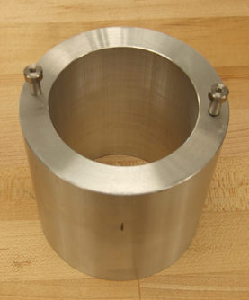
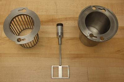
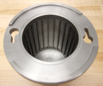
The Building Material Cell is designed for use with the Peltier Concentric Cylinder jacket and comprises a cup with an inner cage, and a single open blade mixing geometry. It is designed for materials with large particles.
Since the flow is complex and the material usually behaves in a non-linear fashion, the calculation of a true or representative deformation, or deformation rate, for the mixing element is an issue. Based on a concentric cylinder analogy, average deformation and stress coefficients can be determined, which relate the motor rotation speed to the material deformation rate and the measured torque to the stress.
The concentric cylinder analogy assumes the open paddle mixing device, in a mixing chamber, to be a virtual cylinder in a cylindrical chamber. The analogy consists of determining an equivalent inner cylinder with a radius Ri, and the same height as the paddle, which generates the same torque, M, at the same rotational speed, N. The outer cylinder of the cup has the same radius as the outer cylinder of the equivalent concentric cylinder system.
Since the equivalent inner radius varies only slightly with the power law index, n, a calibration procedure can be used for the mixing element using a Newtonian or a well-characterized power law fluid.
Once Ri has been obtained, shear rate and shear stress can be calculated as a function of the radius r.
Ait-Kadi, et al. have shown, that at a given radius r*=( Ri+Re)/x*, where x*=2 for small gaps ( Ri/Re>0.9) the shear rate is essentially independent of the nature of the fluid, i.e., independent of the local power law index. For large gaps x* becomes greater than 2.
When selecting the test geometry in TRIOS software select Special Geometry and enter the geometry constants given below. These factors were determined with the calibration fluid filled to the top of the cage slots. Refer to application/product note AAN014 for details on calibration of generic mixing geometries. This spreadsheet provides a template for this calibration of the building material cell using a 10 000 CP oil with the 28 mm standard bob (PN 546016.901). \Copy the test results into the spreadsheet to obtain the correct geometry constants. Follow the instructions in the spreadsheet.
Note that the constants below are approximate values for the building material cell. Recalibration is required for more accurate constants.
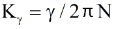
Strain Constant
|
Stress Constant
|
VariablesK= Stress Constant K = Strain Constant N = Rotational Speed T = Torque |
|
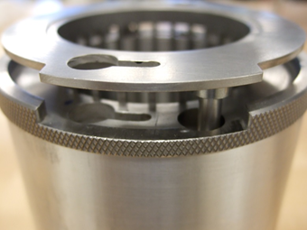
Fit the cage in the cup so that the flange of the cage sits down flush on the top of the cup and the clamping holes align.
To aid cleaning, or if your material is difficult to remove, the cell cup can be lined with overhead transparency film (~0.09 mm thick) cut to size. This will require a rectangle 181 mm x 72 mm and a disk 57.5 mm in diameter.
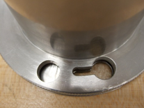
A tool is also provided in the kit to aid cage extraction. Once the cup and cage are removed from the Peltier Concentric Cylinder jacket and placed in the tool (shown in the image below) the protruding dowels should engage with recesses in the cage. Pushing down on the cup will then separate the two components enough to allow the two parts to be taken apart for cleaning. Cleaning tip: If the cup has been lined, and the cup and cage are removed from the tool and inverted prior to final separation, very little sample should be left in the cup.